
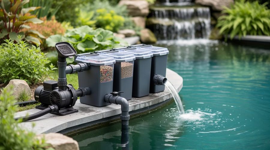
How to Set Up a Pond Filtration System: Diagram and Step-by-Step Assembly
A pond filtration system diagram maps the flow of water from your pond through mechanical, biological, and sometimes chemical filters before returning clean. Reading one correctly means identifying the pump location, understanding the sequence of filter chambers, and recognizing the return path that completes the circulation loop. Most diagrams follow a left-to-right or bottom-to-top flow pattern, with arrows showing water movement and labels marking each component.
If you’ve stared at a filtration diagram and felt lost, you’re not alone. I spent my first season misinterpreting the gravity-feed arrows in a multi-chamber setup, which led to installing my bio-filter upside down. The water pooled exactly where it shouldn’t, and my koi weren’t thrilled. That mistake taught me the single most important rule: always trace the flow path first, then identify components second.
The beauty of a good diagram is that it answers three questions at once. Where does dirty water enter the system? What happens to debris and dissolved waste at each stage? How does clean water return to support fish and plants? These visual guides compress hours of trial and error into a single glance, showing you not just what to buy but how everything connects in the real world.
Whether you’re planning a new pond or troubleshooting an existing setup that isn’t clearing algae, understanding filtration diagrams saves time and money. They reveal why placement matters, why skipping a pre-filter clogs your bio-media, and how gravity or pump pressure dictates your options. In the next sections, we’ll break down each symbol, walk through assembly step by step, and highlight the pitfalls that trip up even experienced water gardeners.
Understanding Your Pond Filtration System Components
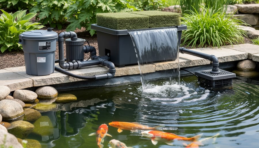
When you look at a pond filtration diagram for the first time, you’ll see several boxes and lines that might seem complicated, but each component has a straightforward job. Understanding what these parts do makes the installation process much less intimidating and helps you choose the right setup for your pond.
The pump sits at the heart of every system. It pulls water from your pond and pushes it through the filtration stages before returning it clean. You’ll see it drawn at the pond’s edge or submerged in the deepest area. Think of it as the engine that keeps everything moving. Without adequate flow, the other components can’t do their work.
Next in line is the pre-filtersometimes called a skimmer or settling chamber. This catches leaves, twigs, and large debris before they clog your main filters. Diagrams often show it as the first box after the pump. It’s your first line of defense and saves you hours of maintenance on downstream components.
The mechanical filter appears next in most diagrams. This stage uses foam pads, filter brushes, or matting to trap smaller particles like fish waste and uneaten food. You’ll clean this component most frequently since it captures the visible dirt that clouds your water. Many pond keepers discover significant external filter benefits at this stage, as these units are easier to access and service than in-pond alternatives.
The biological filter looks similar in diagrams but serves a completely different purpose. It houses special media where beneficial bacteria colonize and convert toxic ammonia from fish waste into harmless nitrates. This invisible process is critical for fish health. Diagrams typically show this as a large chamber with porous media inside.
A UV clarifier might appear as a cylinder between filtration stages. It doesn’t filter anything, but uses ultraviolet light to clump green algae particles together so your mechanical filter can catch them. It’s optional but transformative for chronically green ponds.
Finally, return lines complete the circuit, shown as arrows flowing back to the pond. These might feed a waterfall, fountain, or simple pipe outlet. The diagram shows where clean water re-enters, creating circulation that prevents stagnant zones.
Reading and Interpreting Filtration System Diagrams
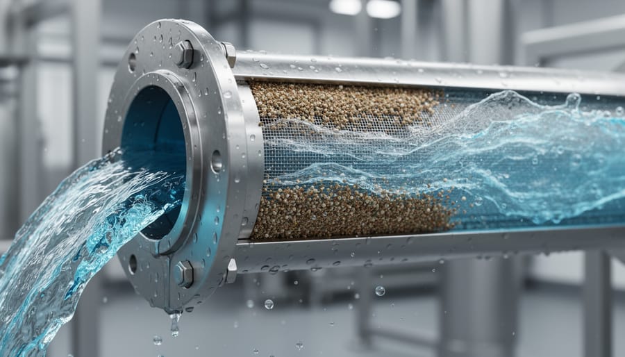
Most pond filtration diagrams use simple visual conventions that become second nature once you know what to look for. Start by following the arrows, which show the direction water travels through your system. Thick arrows usually represent the main flow path, while thinner arrows might indicate secondary flows or overflow routes. You’ll often see the pump marked as the starting point, with arrows showing water moving upward through filters and eventually returning to the pond.
Connection points appear as circles, dots, or small boxes where pipes join components. Solid lines represent hard plumbing like PVC pipe, while dashed or wavy lines typically show flexible tubing. Pay close attention to any measurements marked on these lines, as they indicate pipe diameter, which directly affects flow rate and system performance. A mismatch here causes frustration later when parts don’t fit or your pump can’t push water through undersized lines.
Elevation matters more than most beginners realize. Diagrams often show components at different heights, not just for visual clarity but because gravity and pump pressure work together in your system. If a bio-filter sits higher than the pond’s water level in the diagram, that’s intentional: it prevents backflow and creates proper drainage during cleaning. Check for elevation markers or notes about placement above or below pond level.
Common symbols include check valves (shown as arrows inside circles), T-fittings (illustrated as branching lines), and ball valves (rectangles across the flow line). UV clarifiers often appear as cylinders with wavy lines inside, representing the UV bulb. When adapting a diagram to your specific pond, sketch your actual layout first, noting where your pump location differs or where you’ll add features like waterfalls. Adjust pipe runs and component positions while maintaining the same flow sequence shown in the original diagram. The order of filtration stages matters far more than their exact spacing.
Tools and Materials You’ll Need
Gathering everything before you start saves frustration and prevents mid-project trips to the hardware store. Here’s what you’ll need, organized by the filtration stages shown in most pond diagrams.
Filtration Equipment and Components
- Pond pump: sized for your pond volume (calculate gallons and match GPH rating; most systems need the pump to cycle total volume every 1-2 hours)
- Mechanical filter box or skimmer: captures leaves and debris before they reach biological media
- Biological filter chamber: houses beneficial bacteria colonies; size depends on fish load and pond gallons
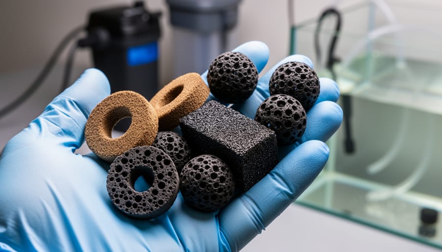
- Filter media: bio-balls, ceramic rings, matala pads, or lava rock for bacteria colonization
- UV clarifier (optional): match wattage to flow rate, typically 10-15 watts per 1000 gallons for algae control
Plumbing Supplies
You’ll need flexible PVC tubing or rigid pipe in diameters matching your pump output (commonly 1.5″ to 2″). Pick up hose clamps, barbed fittings, elbow connectors for direction changes, and PVC primer and cement if using rigid pipe. A ball valve or gate valve lets you control flow for maintenance. Teflon tape seals threaded connections without leaks.
Tools
Have a hacksaw or PVC cutter for sizing pipes, adjustable wrenches for tightening fittings, and a drill with hole saw bits if you’re cutting through liner or filter boxes. A level ensures proper slope for gravity drainage. Work gloves protect your hands, and a tape measure keeps everything accurate.
Optional Items for Advanced Setups
Pressurized bead filters require a backwash valve assembly. Multi-chamber bio-filters benefit from internal baffles (cut from egg crate or plastic sheets). For bottom drains, you’ll need specialized bulkhead fittings and a separate settling chamber or vortex filter.
Safety Precautions Before You Begin
Before you touch any equipment, understand that pond filtration installation combines electricity with water, a potentially lethal mix if handled carelessly. Every pump, UV clarifier, and powered filter must plug into a GFCI (Ground Fault Circuit Interrupter) outlet that cuts power instantly if water contact creates a fault. If your outdoor outlets aren’t GFCI-protected, have a licensed electrician install them before you begin. NEC Article 680 requires GFCI protection for all outdoor water feature electrical circuits, and ignoring this code can result in serious injury or death.
Heavy filter units pose serious lifting risks. Biological filter chambers filled with media can weigh 50 pounds or more, and wet mechanical filters become awkward to handle. Bend at the knees, get help for anything over 30 pounds, and clear a stable path before moving equipment.
Watch for sharp edges on pond liner, filter housings, and cut PVC pipe. Wear gloves when handling liner seams and deburr all pipe cuts before assembly to prevent cuts and abrasions.
If you’re modifying an existing system with fish present, never shut down filtration for more than two hours. Prepare a temporary aeration source, and consider moving fish to a holding tank during major plumbing changes. Drain work areas carefully to avoid flooding surrounding landscapes or washing debris back into the pond.
Step-by-Step Assembly of Your Pond Filtration System
Step 1: Positioning and Installing Your Pump
The pump is the heart of your filtration system, and placement determines how efficiently everything else operates. Start by identifying the deepest area of your pond, this is where your pump belongs. Placing it at the lowest point ensures consistent water intake even when water levels fluctuate and prevents your system from running dry during hot summer months.
For submersible pumps (the most common choice for backyard ponds), set the unit directly on the pond bottom or elevate it 2-4 inches on bricks or a pump stand. This elevation prevents debris from clogging the intake while keeping the screen below the surface. Position it away from pond walls and liner folds to avoid damage and ensure unrestricted water flow.
Check your diagram’s flow arrows, the pump should face toward the filtration path. Secure the intake hose firmly to prevent disconnection under pressure, using hose clamps rated for continuous underwater use. If your diagram shows an external pump, install it below the waterline in a weatherproof housing beside the pond, ensuring it can be primed and doesn’t lose suction.
Never bury electrical cords underwater. Route them safely to a GFCI-protected outlet, leaving enough slack for seasonal maintenance without strain.
Step 2: Connecting the Pre-Filter and Mechanical Filtration
Connect your pump’s outlet to the pre-filter inlet using flexible PVC or corrugated pond tubing. Most diagrams show the pre-filter positioned slightly above pond level to prevent backflow during pump shutdowns. Secure all hose connections with stainless steel clamps, finger-tight isn’t enough when you’re dealing with several hundred gallons per hour.
Your mechanical filter stage catches leaves, fish waste, and other solids before they clog biological media downstream. Position the filter basket or foam pads where you can reach them easily for weekly cleaning during active months. Many pond keepers place this stage near a path or deck rather than burying it behind plantings they’ll trample later.
Run the outlet from your mechanical filter toward the biological stage, maintaining a gentle downward slope to prevent air pockets. Avoid sharp 90-degree turns that restrict flow. If your diagram shows unions or ball valves between stages, install them now, you’ll appreciate being able to isolate sections for maintenance without draining the entire system. Double-check that all threaded connections are hand-tight plus a quarter turn with a wrench, not overtightened to the point of cracking fittings.
Step 3: Setting Up Biological Filtration Media
Biological filtration is where the real magic happens, beneficial bacteria convert harmful ammonia and nitrites into safer nitrates. Position your bio-filter chamber after mechanical filtration so solids won’t clog the media. Most diagrams show a dedicated container filled with specialized media: ceramic rings, bio-balls, lava rock, or structured plastic matting all work, but choosing the right filter media for your pond size and fish load makes a huge difference in performance.
Fill the chamber loosely, never pack it tight, so water can flow through without creating dead zones. The diagram’s flow arrows should show water entering at the bottom and rising through the media, which keeps it oxygenated and prevents anaerobic pockets that produce toxic gases. Leave enough headspace for easy removal during cleaning, though you’ll clean bio-media sparingly compared to mechanical stages. Connect the outlet to your UV clarifier or return line, ensuring no air locks form in the plumbing. Once water flows through, beneficial bacteria will colonize over the next two to six weeks.
Step 4: Adding UV Clarification (Optional)
UV clarifiers tackle green water algae by exposing pond water to ultraviolet light as it flows through a sealed chamber. If your diagram includes this component, install it after mechanical filtration but before the water returns to your pond, this placement ensures the UV lamp sees pre-filtered water, maximizing contact with free-floating algae cells.
Mount the unit horizontally with flow arrows matching your pump’s direction. Check the manufacturer’s flow rate specs: most UV clarifiers work best at 50-150 gallons per hour per watt. A pump pushing water too fast won’t give the UV enough contact time to kill algae effectively.
Position the clarifier where you can easily access both ends, you’ll need to remove the quartz sleeve for cleaning every 4-6 weeks and replace the UV bulb annually. Leave at least 12 inches of clearance around the unit. Connect inlet and outlet using the same diameter tubing as your main flow line to prevent pressure drops that reduce efficiency.
Step 5: Creating the Return Flow to Your Pond
The final step closes the filtration loop by directing clean water back into your pond. You’ve got several options here, each offering different pond aeration benefits. A simple return line positioned just below the surface creates gentle circulation while minimizing splashing. For better oxygenation, elevate the outlet above water level to create a small waterfall effect or install it to feed an existing waterfall feature, the tumbling action dramatically increases oxygen exchange.
Fountain heads and spray patterns add visual appeal while aerating effectively, though they work best in smaller ponds where wind won’t disrupt the display. Position your return opposite the pump intake to establish a full circulation pattern that prevents dead zones. Secure all return plumbing with appropriate clamps and supports so water pressure doesn’t shift connections over time. Test the flow direction by watching how debris moves, you want consistent surface current that sweeps the entire pond toward the intake area, completing the filtration cycle efficiently.
Testing Your System and Verifying Proper Flow
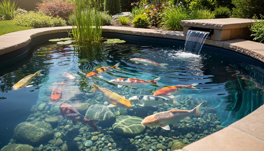
Once your filtration system is assembled according to the diagram, you need to verify everything works before introducing fish. Start by filling the system and turning on the pump, then watch the water’s path through each stage. You should see a steady, consistent flow from the pump intake through the pre-filter, into the biological chamber, past the UV unit if installed, and back into the pond without any stuttering or air pockets.
Check each connection point systematically for leaks, starting at the pump outlet and working your way through the entire circuit. Small drips often appear at hose clamps or threaded fittings, tighten these while the system runs. Look underneath filter chambers and around union connections where leaks hide initially. A properly sealed system stays dry around all joints after 15-20 minutes of operation.
Verify your flow rate matches what the diagram specified for your pond size. Most pumps display their output in litres per hour, and you can roughly confirm this by timing how long it takes to fill a bucket from the return line. Your biological filter needs adequate contact time with the water, too fast means bacteria can’t process waste effectively. Consult your filter manufacturer’s recommended flow rate and adjust the pump’s valve or speed setting if needed.
Listen to your system carefully. A healthy setup produces a low, steady hum from the pump and gentle water movement. Gurgling usually means air trapped somewhere in the line, while grinding or labouring sounds suggest the pump is working against a blockage. If the return flow seems weak compared to what your pump should deliver, backtrack through each stage to find restrictions, a clogged pre-filter or kinked hose often causes reduced output.
Run the system for at least 24 hours before conducting water quality testing or adding any fish. This break-in period lets you spot problems like slow leaks and ensures the biological filter media gets fully saturated. Watch for water bypassing any filtration stage, which means you’ve missed a connection or have an incorrectly positioned valve. Every drop should follow the path your diagram shows, with no shortcuts back to the pond.
Innovative Filtration Techniques to Enhance Your System
The basic three-stage filtration diagram works for most ponds, but several advanced techniques available in 2026 can dramatically improve water quality beyond what traditional mechanical-biological-UV setups deliver. These innovations address specific challenges like fine particle removal, increased bio-capacity, or space constraints that standard diagrams don’t solve.
Pressurized bead filters combine mechanical and biological filtration in a compact, sealed unit that forces water through thousands of plastic beads. The pressure design means you can install the filter below pond level and still pump water to elevated waterfalls, solving the gravity-flow limitations of open filter boxes. They backwash easily with a valve turn, making maintenance quicker than cleaning traditional media chambers. Consider pressurized bead filters when your pond is small to medium-sized and you want a clean, hidden installation with minimal footprint.
Vortex settlement chambers use circular flow patterns to spin heavier particles outward where they drop into a collection zone before water enters your bio-filter. This pre-filtration technique dramatically reduces solids reaching your biological media, extending cleaning intervals and preventing clogging. A well-designed vortex chamber removes up to seventy percent of settleable solids, which means your main filter works more efficiently and beneficial bacteria colonies face less competition from debris.
Modern pond filtration innovations worth considering include:
- Moving bed bio-reactors with free-floating media that maximize surface area for bacterial colonization while self-cleaning through constant motion
- Multi-chamber gravity-fed systems that separate settlement, mechanical screening, and biological stages for superior clarity
- Integrated UV-ozone combinations that tackle both green water and pathogen control more effectively than UV alone
- Automated backwash controllers that maintain peak filter performance without manual intervention
These advanced techniques shine when standard filtration struggles with persistent cloudiness or when you’re implementing algae solutions that require exceptionally clean water. Moving bed reactors particularly excel in heavily stocked koi ponds where ammonia conversion needs exceed what static media can handle.
The investment makes sense when your pond exceeds 10,000 liters, supports valuable fish, or when you’ve maximized your current system and still face water quality issues. Start with the diagram-based basics first, then upgrade strategically based on what your specific pond reveals it needs.
Common Mistakes When Following Filtration Diagrams
Even well-designed filtration diagrams can lead DIYers astray if you don’t adapt them to real-world constraints. The most frequent mistake I see is using an undersized pump because the diagram shows a generic “pump” symbol without specifying gallons per hour. Your pump needs to turn over your pond’s entire volume at least once every two hours, so a 2,000-gallon pond requires a minimum 1,000 GPH pump, but many beginners grab whatever they have on hand. That weak flow starves the biological filter of oxygen and lets debris settle in lines instead of reaching the mechanical stage.
Incorrect plumbing heights cause just as many headaches. Diagrams often show filters at pond level, but if you place your mechanical filter below the water surface without a check valve, it’ll siphon your pond dry when the pump stops. I learned this the hard way during my first installation. Gravity-fed systems need the biological chamber above the mechanical stage so water flows downward through media, not the reverse.
Skipping stages is tempting when you’re trying to save money, but bypassing the pre-filter sends large debris straight into your expensive bio-media, clogging it within days. Similarly, choosing the wrong media because it looks similar in the diagram, like using filter floss where you need K1 micro beads, prevents beneficial bacteria from colonizing properly. The diagram shows what goes where, but you need to research each media type’s actual function before substituting.
Maintenance Schedule and Next Steps
Your filtration system is installed and running, now the real work begins. That first clean water you see won’t last without a consistent maintenance routine.
First Two Weeks: The Cycling Period
Don’t add fish immediately. Your biological filter needs time to develop beneficial bacteria colonies that break down ammonia and nitrites. Run the system empty for three to five days, then introduce a few hardy fish or add pure ammonia to feed the bacteria. Test water daily with a liquid test kit. You’ll see ammonia spike, then nitrites rise as different bacteria populations establish themselves. Full cycling typically takes 10 to 14 days in warm weather, longer in spring or fall.
Your Ongoing Maintenance Calendar
Clean mechanical filter pads and pre-filters weekly during summer, every two weeks in cooler months. Rinse them in pond water, never tap water, chlorine kills the bacteria you’ve worked to cultivate. Check pump intake screens at the same time.
Monthly, inspect all plumbing connections for leaks and verify flow rates haven’t dropped. Replace UV bulbs annually even if they still glow; their algae-fighting effectiveness diminishes after one season of use. Clean quartz sleeves surrounding UV bulbs every month.
Never clean biological media unless flow becomes severely restricted. Those brown, slimy surfaces are exactly what you want. When cleaning is necessary, rinse only half the media at a time to preserve bacteria populations.
Seasonal Adjustments and Upgrades
Reduce pump flow by 30 to 40 percent when water temperatures drop below 50°F. Fish metabolism slows, and over-filtration can stress them. In spring, gradually increase flow as temperatures rise.
Consider upgrading if you’re cleaning mechanical filters more than twice weekly or if fish show stress despite regular maintenance. Your pond may have outgrown its filtration capacity.
Frequently Asked Questions
Diagrams are fantastic guides, but every pond is unique, and DIYers often hit the same snags when translating a generic schematic to their backyard reality. Here are the answers to questions I hear constantly from first-time installers.
Can I modify the diagram for my pond shape?
Absolutely. The diagram shows flow principles and component order, not a rigid blueprint. You can adjust hose lengths, change angles, and relocate components as long as you maintain the proper flow sequence from pump through filtration stages and back to the pond.
How long before the filter is fully effective?
Mechanical filtration works immediately, but biological filtration needs four to six weeks for beneficial bacteria to colonize the media. Your water won’t be crystal clear overnight, so be patient during the cycling period.
What if my pump location doesn’t match the diagram?
Move the pump to where it works best for your pond, whether that’s a different corner or depth. Just make sure your hoses can reach the first filter stage without kinking, and adjust the return line accordingly.
Do I need all the components shown?
The pump and biological filtration are essential. Pre-filters and UV clarifiers are highly recommended but technically optional, especially if you have a lightly stocked pond with good plant coverage.
Another concern that pops up is whether the diagram’s pump size matches your pond volume. If the diagram suggests a 2,000 GPH pump but your pond is 1,500 gallons, you’re fine. It’s better to have slightly more flow capacity than less, and you can always throttle it back with a valve if circulation feels too strong.
Some folks worry about winter operation when half the components shown will freeze in their climate. That’s valid. Shut down and drain external filters before the first hard freeze, bring UV units indoors, and consider running just the pump under the ice in spring-fed ponds. The diagram represents warm-season operation, so adapt your setup seasonally rather than assuming it runs identically year-round. Your pond will guide you once the system is up and running.
Following a well-designed filtration diagram takes the guesswork out of pond setup and transforms what seems complicated into a manageable weekend project. You now have the visual roadmap and step-by-step knowledge to connect pumps, filters, and return lines with confidence, no plumbing degree required.
Start with a proven diagram that matches your pond size, then adapt it thoughtfully to your specific layout. The flow path matters more than perfect replication. Position your components where they’ll work best for your space while maintaining the filtration sequence shown in the diagram.
Your first installation won’t be perfect, and that’s completely fine. Every experienced pond keeper started exactly where you are now, wrench in hand and diagram at their side. They learned through doing, made adjustments as needed, and eventually watched their murky water transform into the crystal-clear pond they’d envisioned.
Once your system runs smoothly, you’ll understand why visual guides make such a difference. The diagram gives you confidence during installation and becomes your reference for future maintenance. Clear water and healthy fish are waiting on the other side of that first connection. You’ve got this.